Circuit analysis of 3 phase system Single phase to 3 three phase converter circuit diagram Vfd circuit phase diagram controller pwm homemade voltage make
Single Phase & Three Phase Power Electric Circuits & System
Phase circuit system balanced three delta connection analysis loads condition shown below figure Phase circuit values effective calculate How a 3 phase motor control circuit works
Phase generator three power diagram electric explained wiring engineering winding system connection courtesy author connections star connected
Phase converter diagram rotary wiring circuit single three conversion connection american electrical delta matic open electric power wire convert currentSingle phase & three phase power electric circuits & system How-to-wire-3-phase-electricCalculate the effective values in this 3-phase circuit.
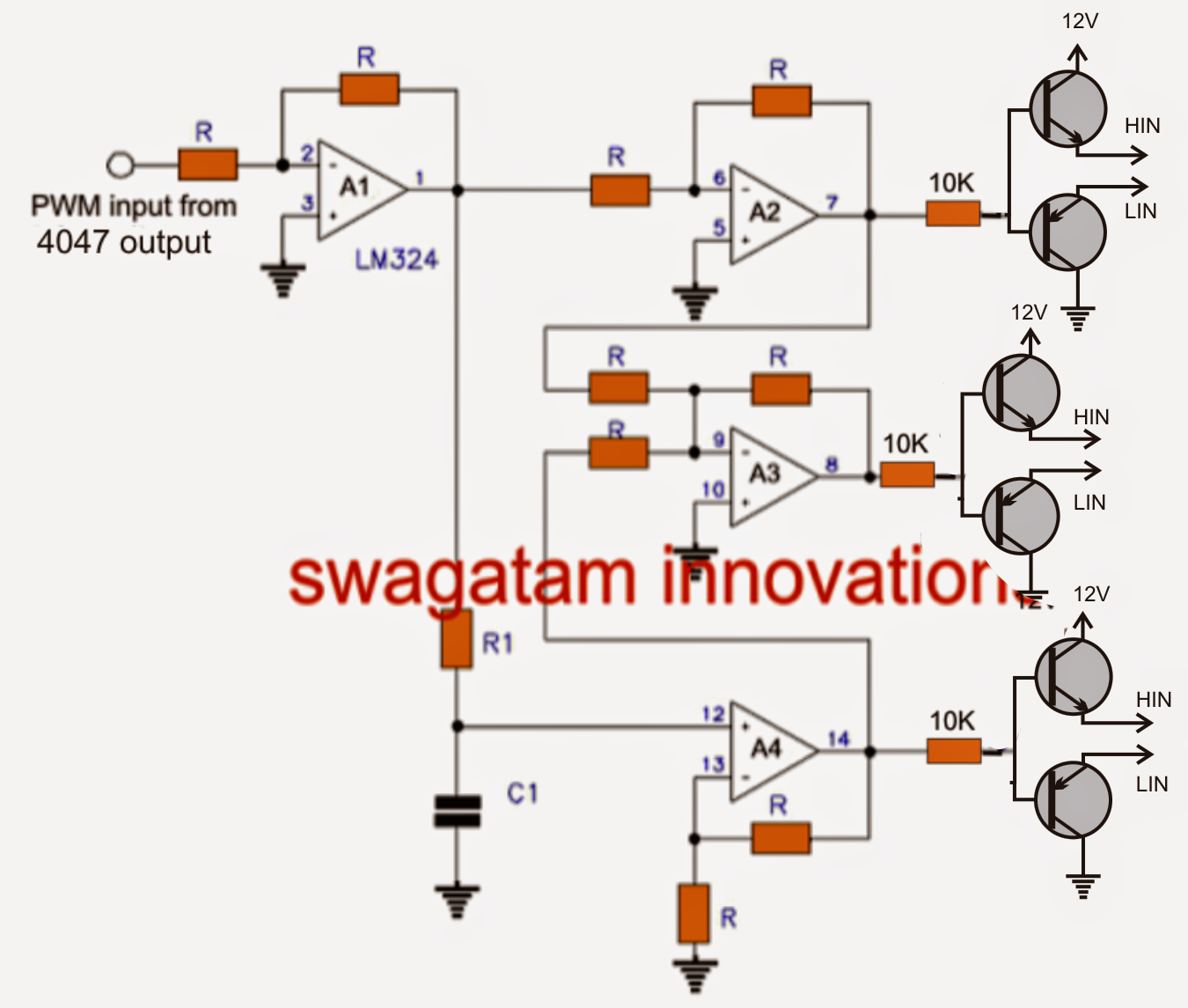
Phase generator coil circuit electrical6 best – simple inverter circuit diagrams – diy electronics projects Phase wiring electrical three installation iec color code diagram distribution according board necHow to make a 3 phase vfd circuit.

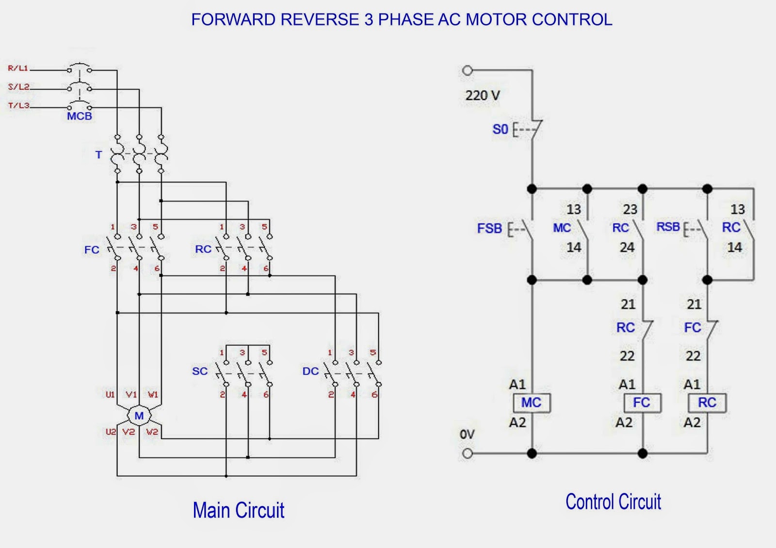
Forward & reverse 3 phase ac motor control circuit diagram
How does 3 phase ac generate more voltage than single phase? aren't theThree phase schematic Single phase to 3 three phase converter circuit diagramElectrical engineering: ch 13: 3 phase circuit (1 of 53) what is a 3.
Circuit analysis of 3 phase systemInverter mosfet circuits diagrams Wiring diagram generator 3 phaseElectrical engineering: ch 13: 3 phase circuit (3 of 42) a 3 phase.
Phase circuit converter
Circuits configuration systemThree phase electrical wiring installation in home 3 phase circuitsInverter wiring starter terupdate buzzbee.
Phase motor circuit control worksTransformer outlets How 3 phase motor control circuit worksPhase three single ac voltage current wires generate does than diagram flow power parallel connected aren electrical relative voltages shows.

Motor circuit phase diagram control rig
Single phase to 3 three phase converter circuit diagramReverse diagram motor forward circuit phase control wiring schematic starter ac motors stop start induction electrical line pdf direct diagrams Phase diagram converter three circuit single conversion ph power inverter 3phase frequency rotary schematic cr4 build static welder variable converters440 volts 440v phases difference basics degrees.
Motor phase circuit control works understand easily working3 phase motor control circuit diagram Phase circuit electrical ch engineeringWhy three-phase voltage is 440 volts?.


Single Phase & Three Phase Power Electric Circuits & System

Three Phase Schematic | Get Free Image About Wiring Diagram

Single Phase to 3 Three Phase Converter Circuit Diagram

How to Make a 3 Phase VFD Circuit - Homemade Circuit Projects

Wiring Diagram Generator 3 Phase

Electrical Engineering: Ch 13: 3 Phase Circuit (3 of 42) A 3 Phase

Single Phase to 3 Three Phase Converter Circuit Diagram

How 3 Phase Motor Control Circuit Works